Flash GLEDOPTO GL-C-310WL
I was recently working on a project that needed an ESP32 powered from a 12 volt source with 4 GPIO PINs, ready-made, and in a case. I started going down the custom built route when I ran across the GLEDOPTO GL-C-310WL for a good price and picked one up to see if it could be re-flashed. The 310WL differs from the 309WL in that the 310L has a built-in I2S microphone, which may be useful for some projects like OpenAI integration, but that’s a future project.
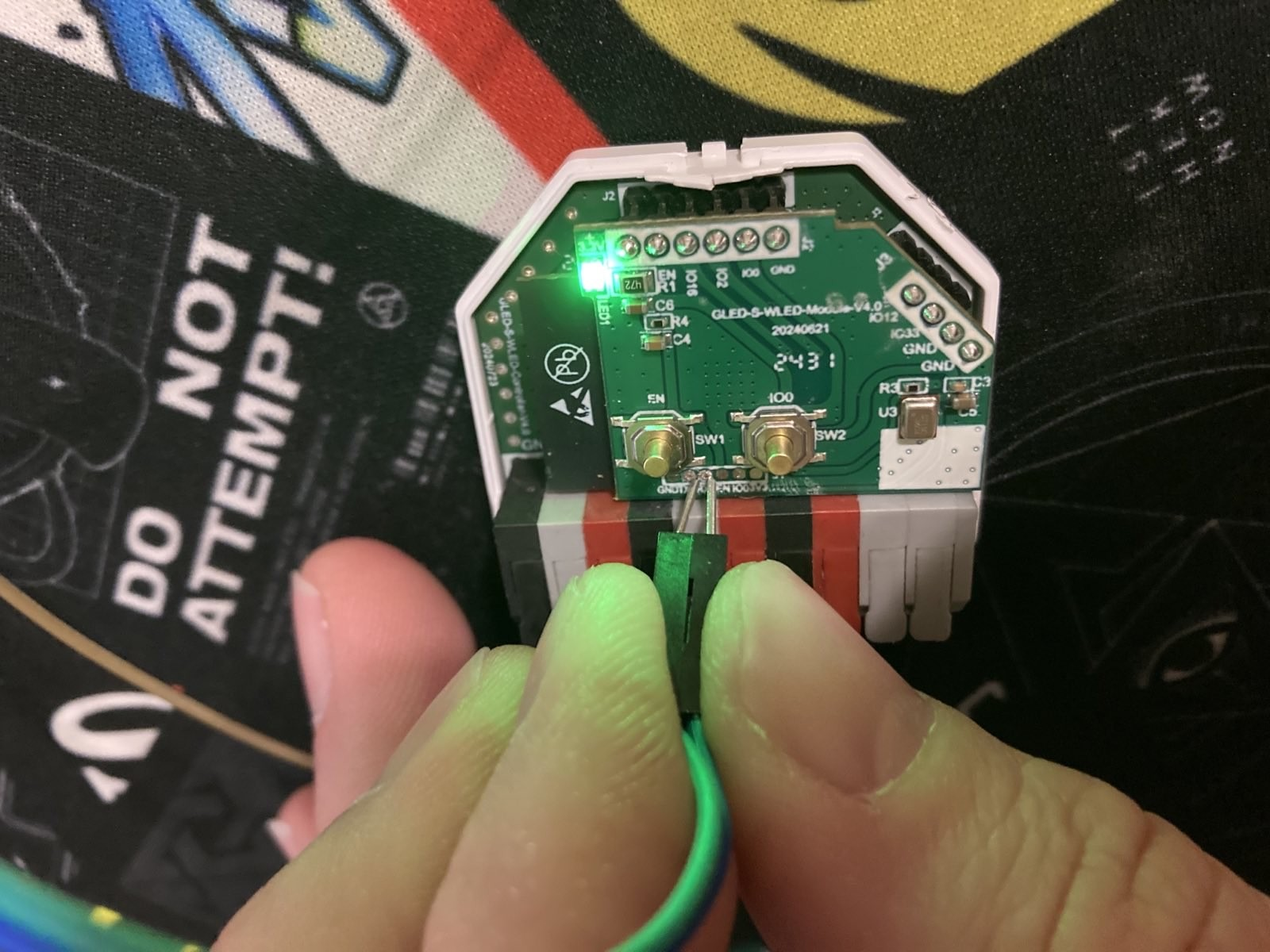
GLEDOPTO was nice enough to leave the test pads exposed and easily accessible when you remove the case. You’ll also notice the buttons are labeled ‘EN’ and ‘IO0’, which are used in the flashing process.

The pins from left to right are:
- GND
- TXD
- RXD
- EN
- IO0
- 3V3
These are almost everything you need to flash the device, but they’re in a 1.25mm pitch REALLY TINY format, so they’ll be hard to work with directly. You can use flying leads or a PCBite, but that introduces complexity and cost.
Since EN and IO0 are connected to the buttons, and 3V3 and GND can be supplied using the Wago-like connectors, you only need UART TX and RX. You can use an FTDI like pictured below, a FlipperZero, an Arduino, ESP32 Dev Board, or an other USB to Serial converter.
The only other wiring that is required is a common ground, and to pull GPIO2 low. GPIO15, GPIO0, and GPIO2 are used to configure the boot mode, and by pulling GPIO2 low we’re able to boot from UART.
For connecting to UART, remember that your TX connects to the devices RX, and your RX connects to the devices TX. You’re Transmitting and they’re Recieving, and you’re Recieving what they’re Transmitting.
The FTDI Adapter can’t support enough current for the ESP32, so you’ll need an external power supply for the board.
Here’s an FTDI wiring diagarm, but other devices will be similar.
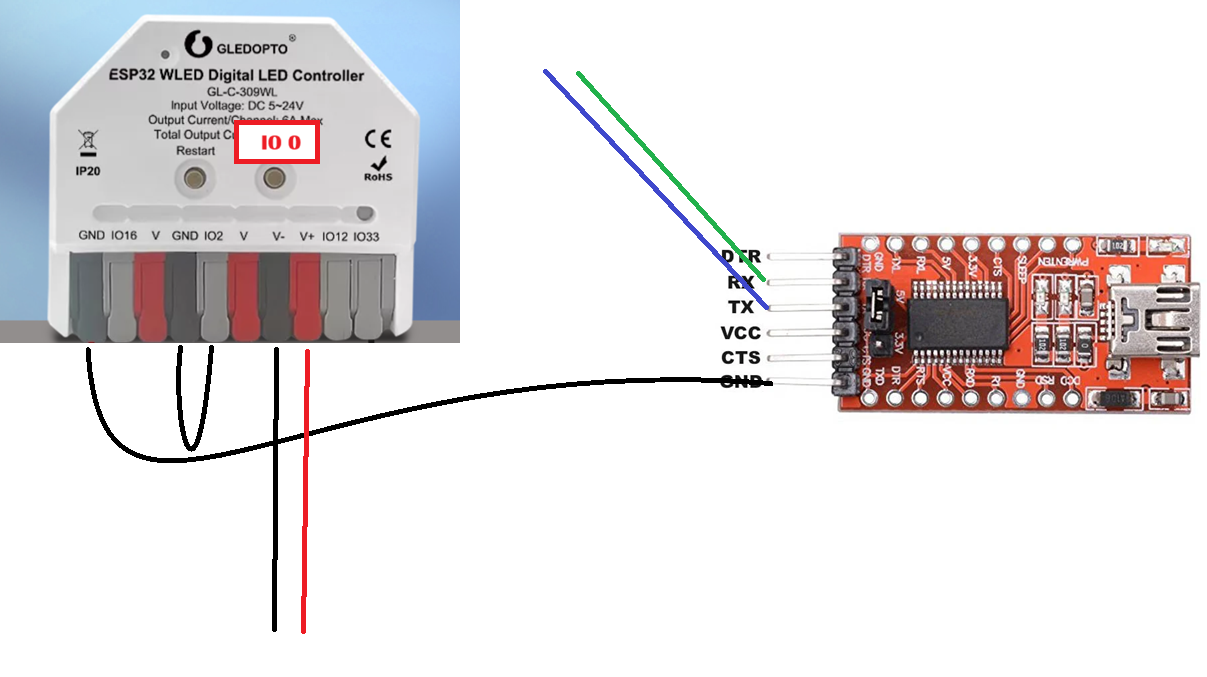
The Green and Blue wires are DuPont calbes, and can have their tips slightly bent towards each other allowing for easier contact with the 1.25mm pitch test pads.
Using a steady hand and a bit of patience, you can hold the DuPont cables on the pads and get a good serial connection.
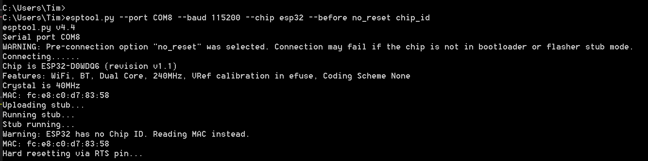
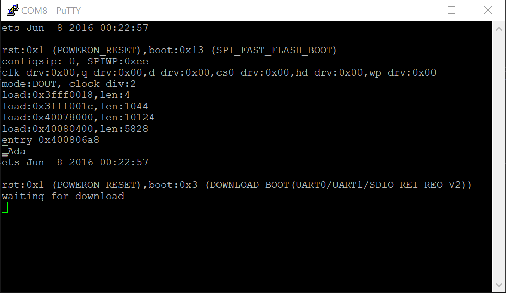
I tested with putty using a speed of 112500 baud to make sure we could see the expected boot messages. To put the ESP32 into Boot from UART mode, you’ll want to hold IO0 (the “Function” button on the GLEDOPTO), while pressing and releasing the EN button (Restart). You should see the ESP32 boot message and “waiting for download.” Espressif provides an explanation on the GPIO pins and boot mode selection.
Close putty or disconnect from the serial port, and then esptool.py can be used to read, erase, or flash the ESP32. By using the --before no_reset flag, esptool won’t reset the ESP32 before trying to upload code.
From here you can flash another image like Micropython or you own code.